SOLIDWORKS | ANSYS | CFD | THERMAL SYSTEMS
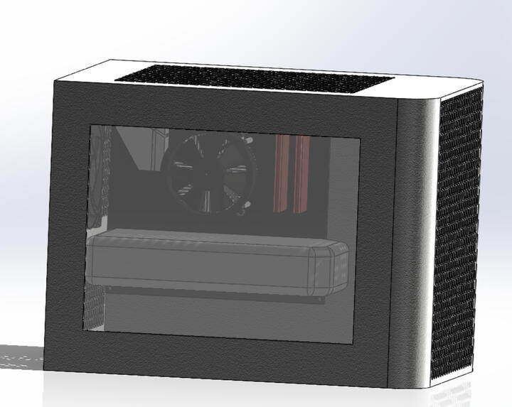
PC: Water Cooling vs. Air Cooling
Analyzed the temperatures in my CPU during high demand gameplay. I modeled my PC using Solidworks and then imported the components into Ansys to determine maximum temperatures experienced by my CPU. The effort of this project is to finally put to rest a question that I've wondered: "Was it worth it to buy a water cooler for my CPU? Does my CPU see lower temperatures now?."(Jan 2024 - Present)
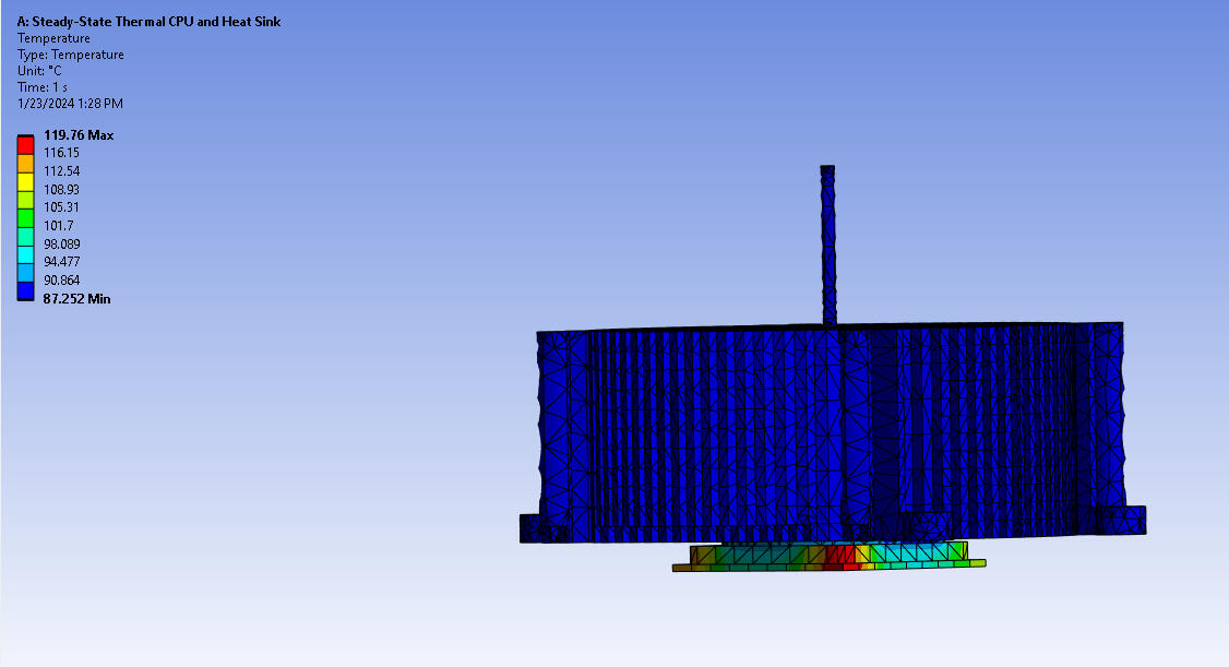
1. Steady-State Thermal
The first simulation was of the CPU and its heatsink, conduction only. No forced air at this point. An internal heat generation of 85W was assigned to the CPU to match to peak power draw of my computer while running a game. It reached a peak temperature of 68°C. This simulation reported a maximum temperature of 119°C. This result validated the need for forced convection (air or water). Temperatures of 100°C can hinder CPU speed and component lifetime.
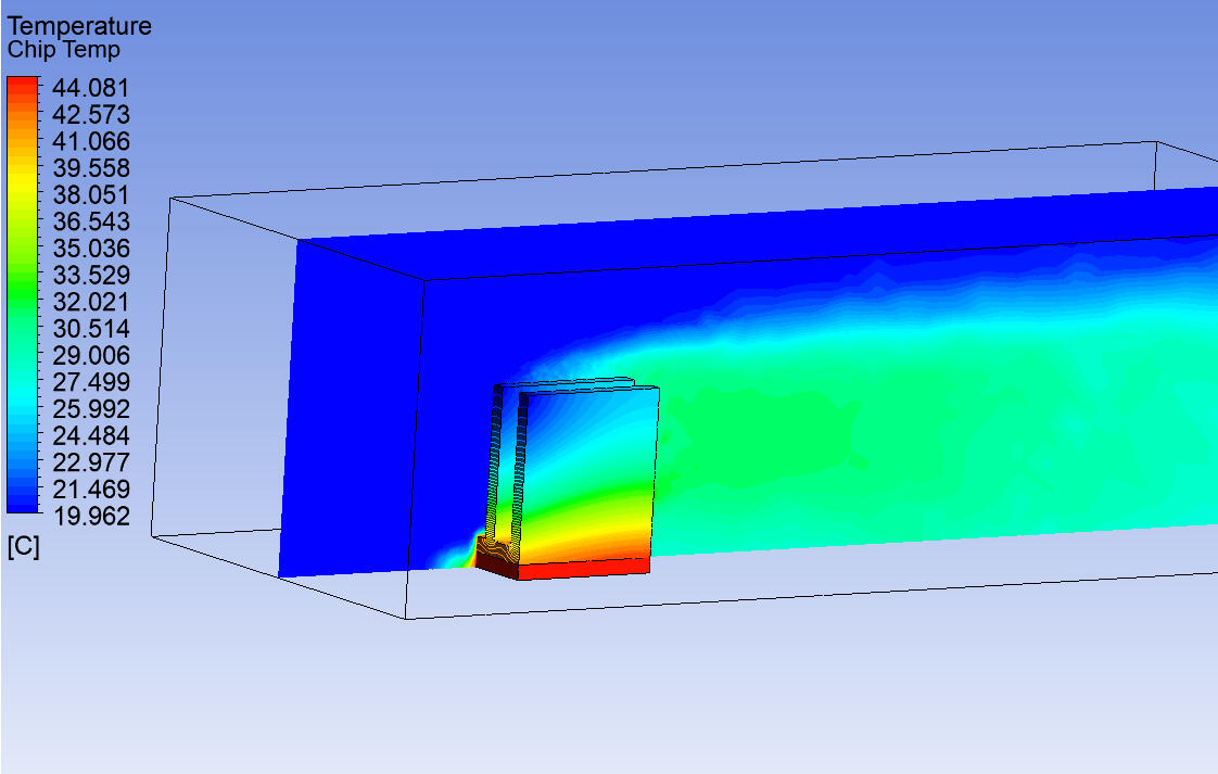
5. CFD Analysis on Simplified Chip and Heatsink
Prior to simulating the complex geometry for the actual heatsink, I performed a CFD simulation on a simple heatsink and chip. This allowed me to refine the analysis process in Ansys Fluent before tackling the challenging geometry. This chip generated 50W of power, the airflow was set to 1 m/s, and the air stream started at 20°C. The max temp seen was just over 44°C.
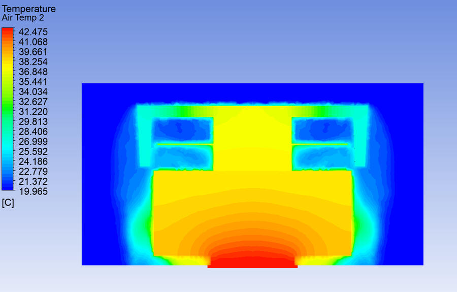
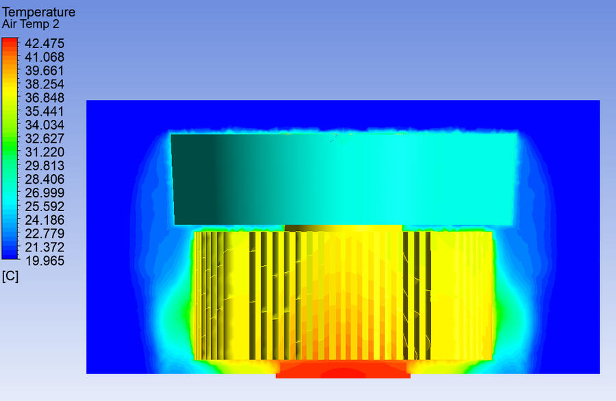
7. CFD Analysis on Actual CPU and Heatsink
I solved the issue with simulating the more complex geometry of the actual heatsink by cutting the model into quarters. Ansys had an easier time meshing a quarter of the assembly, this also helped reduce element count. I applied an 85W heat generation load on the CPU and used an airstream of 1.7 m/s at 20°C to match the specifications of the fan manufacturer (65 CFM). The CPU saw a max temperature of 42.5°C. This is a realistic number that air cooled PC's typically run at under load. This is a clearly demonstrates the efficiency of convection at transferring heat (max temperature was 119°C without convection).
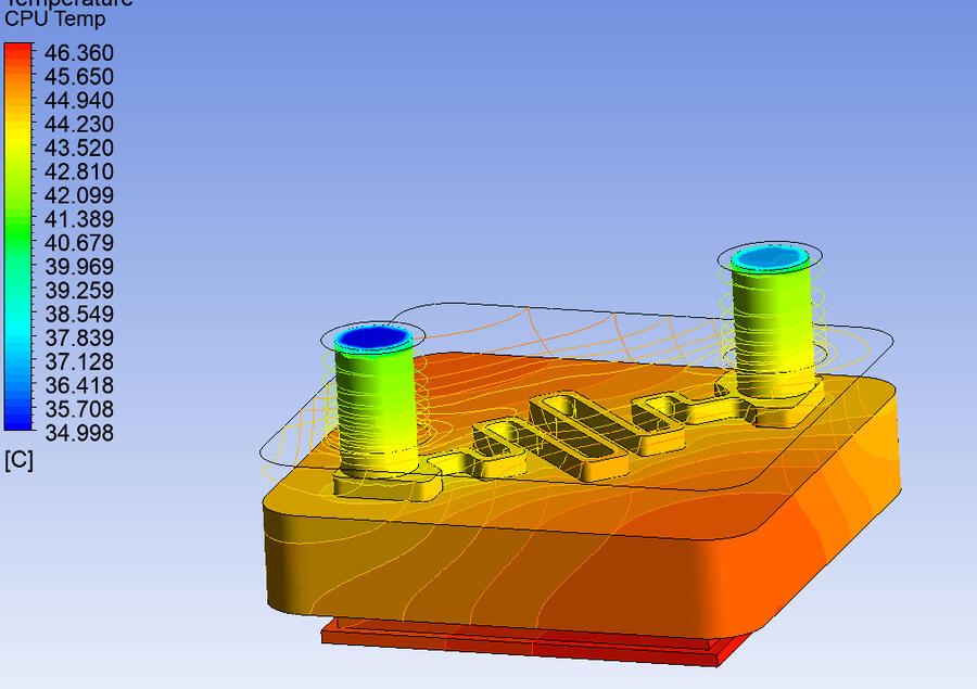
8. CFD Analysis on CPU and Simplified Water Cooling Block
A water block with simplified geometry was created and simulated in ANSYS Fluent. An 85W heat gain in the CPU resulted in a peak temperature of 46.4°C. It is worth noting that the actual water cooler does not have such a thick block. Additionally, boundary conditions need to be reviewed. The below assumptions were made using sample data from other users of CPU water coolers online.Conditions: 0.25 m/s water flow, 35°C entering water temperature.
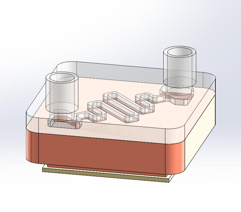
9. Modeling and CFD Analysis on my Actual Water Cooler

With a CFD analysis completed on a simplified water block I am now ready to model my actual water cooler. I will reduce complexity to geometry where possible. The largest changes here will be the the inclusion of fins on the cold plate (right above), this will resulting substantial cooling. The water is drawn along the fins the long way. Additionally, the cooler has a 50 CFM fan on it (above left). I will also be refining boundary and input conditions (investigating actual inlet temperature of water).